Gravel Pack Completion

Gravel pack completion is a common sand control method used to prevent formation sand production from unconsolidated sandstone reservoirs. Sand production blocks tubulars, creates downhole cavities and erodes hardware so it must be separated and disposed of on surface.

A steel screen is placed in the wellbore and the surrounding annulus is packed with prepared gravel of a specific size designed to filter formation sand. The American Petroleum Institute (API) has set the minimum specifications desirable for gravel-pack sand in API RP 58 “Testing Sand Used in Gravel-Packing Operations”. The primary objective is to stabilize the formation while causing minimal impairment to well productivity.

Samples of the formation sand must be evaluated to determine the median grain size diameter and grain size distribution, failure to acquire appropriate samples will result in plugging or the production of sand once again.

Posted in Completion systems, Drilling and production equipment, Petroleum engineering | 1 Comment

Conductor Sharing Wellhead (CSW)

The relatively small footprint on offshore platforms which is divided between living quarters, processing modules, dry trees & wellheads, piping, offices… gives operators limited options in terms of the number of wells to be drilled unless they build larger, expensive ones.

The CSW system enables drilling multiple single or dual completions wells from a single slot saving costs and reducing platform size. Depending on the original equipment manufacturer different sizes, configurations and ratings are available.

Posted in Completion systems, Drilling and production equipment, Petroleum engineering | Leave a comment

Riserless Light Well Intervention (RLWI)

Original equipment manufacturers and oilfield service providers are developing new safe and cost effective ways to implement and execute subsea well interventions without mobilizing expensive drilling and workover rigs.

DP3 special subsea support vessels featuring an active heave compensated crane, a moonpool and a horizontal skidding system to provide safe and efficient movement of subsea equipment modules, work class ROV’s and a RLWI stack are now capable of carrying out well interventions at depths of up to 2,000 m (6,500 ft) and pressures of 10,000 psi.

The umbilical allows the control of the different packages (LLP, WCP…) from the RLWI vessel. The stack has a lubricator system that enables wireline tool strings to be inserted into the wellbore under full pressure. A closed loop circulation system enables the reinsertion of hydrocarbons back into the well, eliminating the need to transfer wellbore fluids to the vessel.

Posted in Subsea engineering | Leave a comment

Umbilical Pre-Commissioning

umbilical

Umbilical represent one of the most critical components of a Subsea field development, unlike other equipment it undergoes extensive testing to confirm the mechanical and structural integrity of associated infield electrical, hydraulic and (in some instances) fiber optic cores. System design and complexity will ultimately dictate the pre-commissioning and testing philosophy.

Pre-commissioning is a suite of tests performed in accordance with ISO 13628-5 from the topsides. Post Hook-Up testing uses temporary equipment set up within close proximity of the hang-off location on the host facility in order to minimize the routing of high-pressure test hoses, in particular away from walkways and adjacent worksites. It may include all or some of the following tests depending on the design:

  • DC resistance testing to confirm the continuity of the electric cable conductors present within the main umbilical and electrical flying leads.
  • Insulation resistance testing (IR) to verify the integrity of the insulation within each electric cable and flying lead. IR testing also confirms the integrity of the subsea electrical connectors and confirms that each connector/connection is free from water ingress.
  • Time Domain Reflectometry (TDR) testing to detect the presence and position of any discontinuities such as kinks, broken conductors and damaged insulation causing low resistance faults within the umbilical cables, and to provide in all cases a ‘signature’ for each cable which can be compared with earlier tests, i.e. those obtained during factory acceptance testing (FAT).
  • Optical Time Domain Reflectometry testing (OTDR) to confirm the integrity and routing of each optical core present within the umbilical. The OTDR utilizes a laser emitting diode to sends short pulses of light down one end of a fiber at a specified wavelength.
  • Pressure leak testing of the low and high-pressure control fluids supply lines, chemical injection/service lines to 1.0 and 1.1 times the design work pressure respectively, to confirm the leak-tight integrity of both the umbilical and the functional connections downstream of the umbilical.
Posted in Subsea engineering | Leave a comment

S-LAY Rigid Flowline Installation Sequence (single joint)

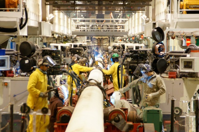
01-pipeline-installation_03a-firing-line-1600x1067

  1. Pipes load out from barge: Using certified and inspected lifting and rigging equipment (crane, shackles, slings, clamps…), a qualified crane operator, make sure the lifting and rigging procedures along with safety instructions are very well understood by all involved personal.
  2. Bevelling: Pipes are transferred to the bevelling station for machining, make sure that the pipe joints are machined as per engineering DWG’s, make sure the appropriate ITP (inspection and test plan) and safety instruction are applied. Make sure the cutting tools wear (how many joints will be machined before tools are permanently replaced or sharpened and reused) and the machine settings are being monitored. Transfer the pipes to line up station or double joint station depending on the vessel technology.
  3. Induction preheating: Cut backs are preheated using electromagnetic induction, make sure the appropriate PPE is being used and safety instruction (high temperature, electric current) are very well understood. Apply the appropriate ITP instruction for temperature monitoring.
  4. First welding station (bead stall): This is one of the most critical steps (root and hot pass) in the pipeline laydown process, make sure the joints are perfectly lined up using internal line up clamps, make sure the appropriate WPS (welding procedure specification) is applied by qualified welders as per AWS and international standards, make sure the appropriate ITP is applied, make sure the appropriate and calibrated equipment are being used, make sure the appropriate PPE is used and safety instruction related to welding and milling are being applied and reminded over and over again (the repetitive nature of the process is good for building up experience and picking up speed but falling into routine is dangerous, we must be mentally present and sharp for our safety).
  5. Different welding stations (filling and cap): make sure the appropriate WPS (welding procedure specification) is applied by qualified welders as per AWS and international standards, make sure the appropriate ITP is applied, make sure the appropriate and calibrated equipment are being used, make sure the appropriate PPE is used and safety instruction related to welding and milling are being applied and reminded over and over again (the repetitive nature of the process is good for building up experience and picking up speed but falling into routine is dangerous, we must be mentally present and sharp for our safety)
  6. Radiographic testing or AUT: This is one of the most critical steps in the pipeline laydown process (in case of rejection the pipe joint is disconnected and introduced in the chain again). Multiple NDE station could exist depending on the process. Make sure the appropriate ITP is being applied, make sure the inspection machine is calibrated and operated by qualified and certified NDE inspectors, make sure the NDE reports are accurate and kept in record. Make sure the appropriate PPE is used and safety instructions are being applied (radioactive material).
  7. Field joint coating stations: The following operations could exist depending on the process:
  • Cooling and abrasive blasting: once the welding process is done the field joint is prepared for corrosion protection and insulation coating (cooled and cleaned). Make sure the machines used are calibrated (flow rate, pressure), Make sure the appropriate ITP is applied, the appropriate PPE must be used and the MSDS whether for the lubricant or abrasive materials is very well understood and applied.
  • Adhesive application and heat shrink sleeve or FBE (fusion bonded epoxy): a corrosion protection coating is applied. Make sure the appropriate ITP is applied, the appropriate PPE must be used and the MSDS for the adhesive is very well understood and applied.
  • High density polyurethane foam injection or injection moulded polyethylene: an insulation coating for flow assurance purposes is applied, make sure the machine is calibrated and the appropriate PPE is used, the MSDS for the materials is very well understood and applied

Fibre optic piggyback installation (optional): fibre optics became one of the most effective real time pipelines monitoring system for over bending and leak detection allowing fast intervention. Apply the appropriate ITP, handle the fibre optic line with care and make sure it is fixed properly and in the correct position to prevent damage (contact with stinger during laydown, crashed under the pipeline…)

Posted in Offshore oil&gas industry, Offshore pipelines, Subsea engineering | Leave a comment

LBL Subsea Positioning System

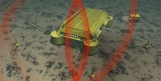
acoustic-positioning

LBL (Long Base Line) positioning systems use a known array of seabed anchored baseline transponders as reference points for navigation,  the distance between these transponders is typically hundreds of meters, much longer than other subsea positioning methods thus the name LBL. The position of a target within the array can then be determined by measuring the distance between itself and each transponder in the array. The LBL technique results in very high positioning accuracy which is independent of water depth.

Posted in Offshore oil&gas industry, Offshore pipelines | 1 Comment

Subsea Pipe Handling Frames (PHF)

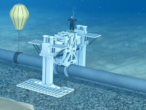
PLF

During Ti-In operation in offshore pipeline construction the PHFs move the pipeline ends into position after the cutting and beveling operations are done. They lift the pipeline sections and shift them sideways to line them up for welding. Lift bags are installed on the segments and filled with air. Once filled, the bags can lift up to 20 tonnes, helping the PHFs to manipulate the extremely heavy pipeline segments.

Posted in Subsea engineering | Leave a comment

PIG launcher & Receiver

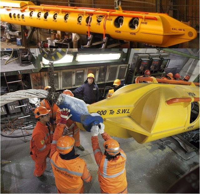
pig-launcher

During the offshore pipeline laydown process hydrotests and inspections are performed on the different pipeline sections, in order to perform these operations a PLR (PIG launcher & receiver) are welded to the both ends of the pipeline. PIG (Pipeline Inspection Gauge) launchers are specialized heads attached to the start of the pipeline section, they house the PIGs that will clean and gauge the sections prior to pressure testing. We should point out that the water introduced into the pipeline section will be filtered and de-oxygenated, it is also treated with ultraviolet light so that it is bacteria free. The pressure test is conducted for at least 24 hours to confirm the pipeline mechanical integrity .

Posted in Offshore oil&gas industry, Offshore pipelines | Leave a comment

Subsea distribution units (SDU)

SDE

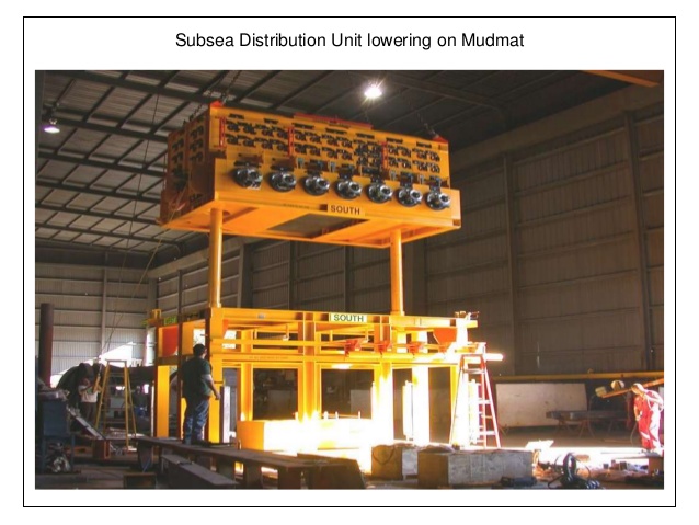
The Subsea Distribution Unit SDU is located on the seabed and provides the hydraulic, chemical and electrical distribution between the SUTA (Subsea Umbilical Termination Assembly) and the rest of the subsea production system. The SDU equiped with MQC (multiple quick connect) plates distributes the hydraulic, chemical and electrical supplies to the flying leads which in turn connect to the subsea trees and manifolds. The SDU is mounted onto a special mounting base which in turn is installed onto a subsea foundation such as a mudmat.

Posted in Offshore oil&gas industry, Subsea controls, Subsea engineering, Subsea structures and equipment | 1 Comment

Free standing hybrid risers (FSHR)

Sans

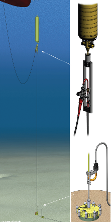
A freestanding hybrid riser (FSHR) comprises a vertical steel section supported at its top end by a buoyancy can, the pull from which provides the system with stability.
The buoyancy can will be on a depth at which the effects of surface currents and Waves are significantly attenuated. A flexible riser connects the end of the vertical section to the floating production unit throughout a top riser assembly. The link between the buoyancy can and the top end of the vertical section of the riser is provided by a tether chain and a tension monitoring system. At the base of the riser we can see the foundation (suction pile) and the lower riser assembly connected to a riser base spool which is the interface between the flowline (PLEM) and the riser.

Posted in Drilling and production equipment, Offshore oil&gas industry, Petroleum engineering, Subsea engineering, Subsea structures and equipment | 2 Comments